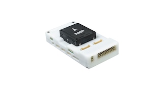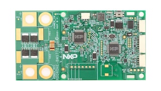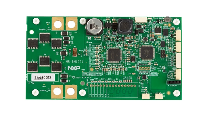
Smart Battery Management for Mobile Robotics 7-14 Cells

Roll over image to zoom in

Block Diagram

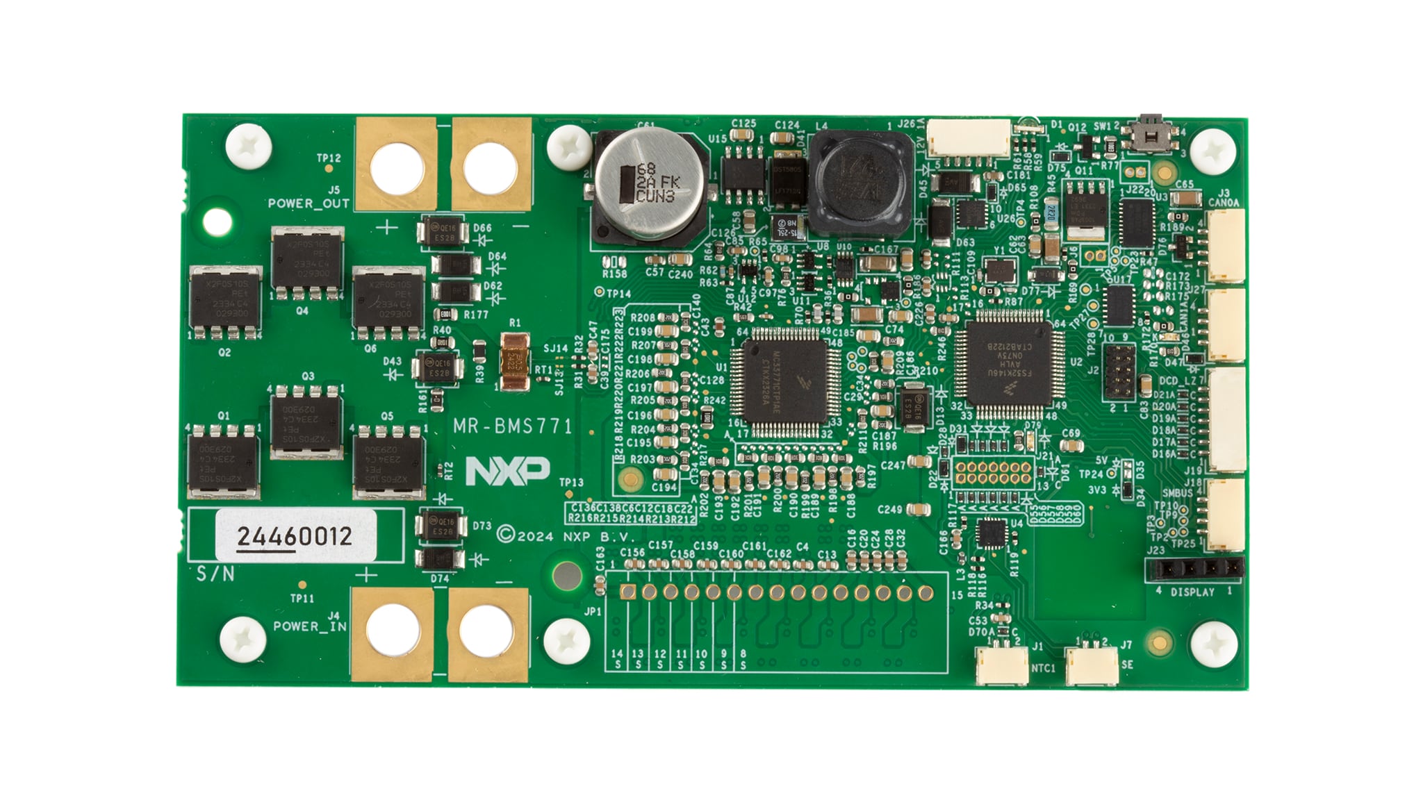
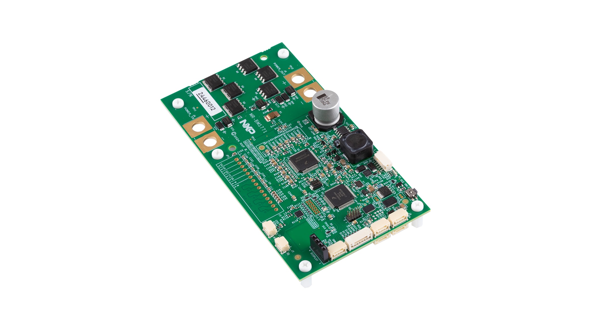
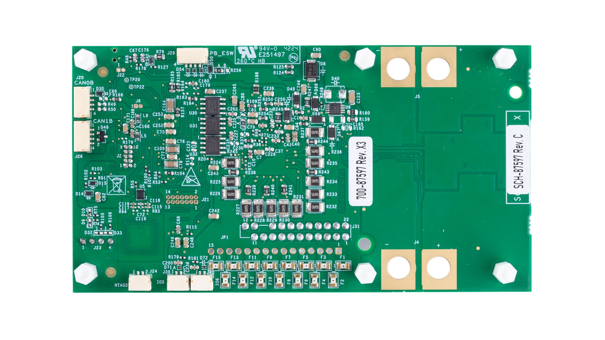
MR-BMS771

MR-BMS771 Block Diagram

Supported Devices

Processors and Microcontrollers

S32K Auto General-Purpose MCUs

Battery Management

Battery Cell Controllers

Security and Authentication

Authentication

RFID

Connected NFC Tags

Interfaces

CAN Signal Improvement

Features

Flexibility

  • MCU-based solution with 7 to 14 cell batteries, with stack voltage ranging from 15 V to 59 V

External 12 V

  • 12 V 1 A output with Over Current Protection (OCP)

Battery Self-Management

  • Performs accurate battery stack and cell voltage measurements as well as accurate battery charge or discharge current measurements, up to 30 A DC tested

Cell Balancing

  • Operates cell balancing during charging

Low Power Modes

  • Offers a deep sleep mode (for transportation and storage) with very low leakage current, as well as an automatic sleep mode with low current consumption on the battery

Safety

  • Allows diagnostics to verify the safe operation of the battery

Diverse Connection Types

  • Two CAN buses are available on the board. Of which 1 CAN Signal Improvement Capability (SIC) up to 8 Mbit/s
  • An I²C interface is implemented on the board and can also be used as a SMBus
  • An external OLED display connected via I²C is provided with the MR-BMS771 kit

NTAG 5 Boost

  • The NTAG 5 boost is optional on the MR-BMS771 board. It also allows the user to acquire data and configure the board through NFC

PCB Antenna

  • An NFC antenna is built on the PCB. It allows short-range NFC communication with a smartphone

External Antenna

  • For extended-range NFC communication, it is possible to connect an NFC antenna as a replacement for the PCB antenna

Secure Element

  • The integrated secure element EdgeLock® SE051C delivers proven security certified to CC EAL 6+, with AVA_VAN.5 up to the OS level, for strong protection against the most recent attack scenarios

SWD and JTAG

  • Both SWD and JTAG debugging interfaces are available on the MR-BMS771 design. They work with standard J-Link as well as other debuggers

DCD-LZ

  • DCD-LZ is a combined debug console interface for use with PX4 DroneCode and HoverGames platforms

S32K146

  • Automotive grade (AEC-Q100 qualified), 32-bit Arm® Cortex®-M4F-based MC
  • 1 MB Flash, 128 K SRAM, 80 MHz @ RUN mode (112 MHz @ HSRUN mode), -40 °C to +105 °C/+125 °C, 64/100/144 LQFP, 100 MAPBGA
  • ISO CAN FD, CSEc hardware security, ASIL B ISO26262 functional safety, ultra-low power performance

Buy Options

MR-BMS771-Image

Click to expand

MR-BMS771
Active

Smart Battery Management for Mobile Robotics 7-14 Cells.

$223.25 USD
In Stock :10
Order from distributors

Documentation

Quick reference to our documentation types

3 documents

Compact List

Design Resources

Related Hardware

Quick reference to our board types.

2 hardware offerings

Design Files

Quick reference to our design files types.

2 design files

Software

Quick reference to our software types.

3 software files

  • Application Example Software

    NuttX RTOS C-Based BMS example for RDDRONE-BMS772

  • Application Example Software

    NuttX RTOS C-Based BMS example for MR-BMS771

  • Application Example Software

    MBDT Toolbox S32K1xx 4.3.3 Patch

Note: For better experience, software downloads are recommended on desktop.

Training

2 trainings

Support

What do you need help with?